- Out-of-Stock
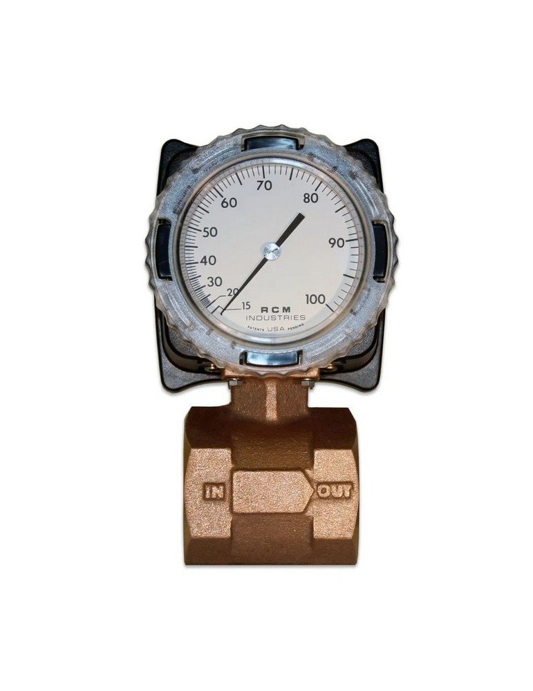
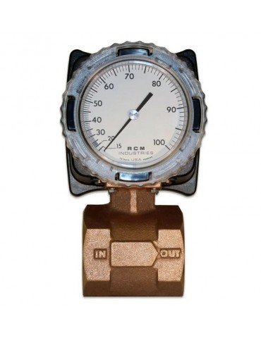



The RCM Flo-Gage differential pressure flowmeter provides a direct local reading of liquid or gas flow. The mechanical indicator operates without external power and can be specified for water, compatible oils, compressed air and other gases.
Check flow directly at the pipeline with the RCM Flo-Gage. Its large analogue dial lets operators read the flow rate during routine inspections, without a separate display or electrical supply for the basic mechanical meter.
Liquid and gas versions are selected and calibrated for the intended service. Specify the fluid, flow range and operating conditions so the scale and construction match the installation.
A calibrated nozzle inside the meter body creates a differential pressure as fluid passes through it. In the mechanical version, opposed bellows sense this pressure difference and move the dial pointer through a linkage.
The scale displays flow directly in the specified engineering units. This integrated arrangement avoids the need to assemble a separate orifice plate and differential pressure indicator.
| Service | Typical applications | Selection details |
|---|---|---|
| Water and cooling circuits | Cooling-water lines, heat exchangers and equipment utilities | Flow range, available pressure and connection size |
| Glycol mixtures and oils | Compatible cooling mixtures, lubricating oils and fuel oils | Composition, viscosity, density and operating temperature |
| Compressed air | Air supply to machines, tools and individual operating areas | Line pressure, temperature and required flow units |
| Other compatible gases | Nitrogen, argon, carbon dioxide and other specified gas services | Gas composition, calibration conditions and material compatibility |
For gas measurement: State whether the required flow units refer to actual line conditions or standard/reference conditions. Changes in gas pressure and temperature can affect the reading and may require correction.
| Series | Connection style | Published size range |
|---|---|---|
| 7000 | Threaded, with NPT or BSP options | 1/4 to 3 inches |
| 8000 | Wafer body installed between compatible flanges | 1/2 to 8 inches |
These are family size ranges. Confirm the available flow scale, material and connection combination for the selected meter.
| Item | Details |
|---|---|
| Measuring principle | Differential pressure across an internal calibrated nozzle |
| Local display | 3.5-inch / 90 mm analogue dial with 270° scale |
| Accuracy | ±3% of full scale under the specified calibration conditions |
| Measuring range ratio | 6:1 |
| Body options | Bronze, Monel or 316 stainless steel, depending on configuration |
| Fluid visibility | Suitable for clear or opaque liquids; measurement does not rely on a sight tube |
| Power supply | Not required for basic mechanical indication; electrical options have separate requirements |
| Pressure and temperature limits | Depend on the selected construction, seals and options; follow the meter nameplate ratings |
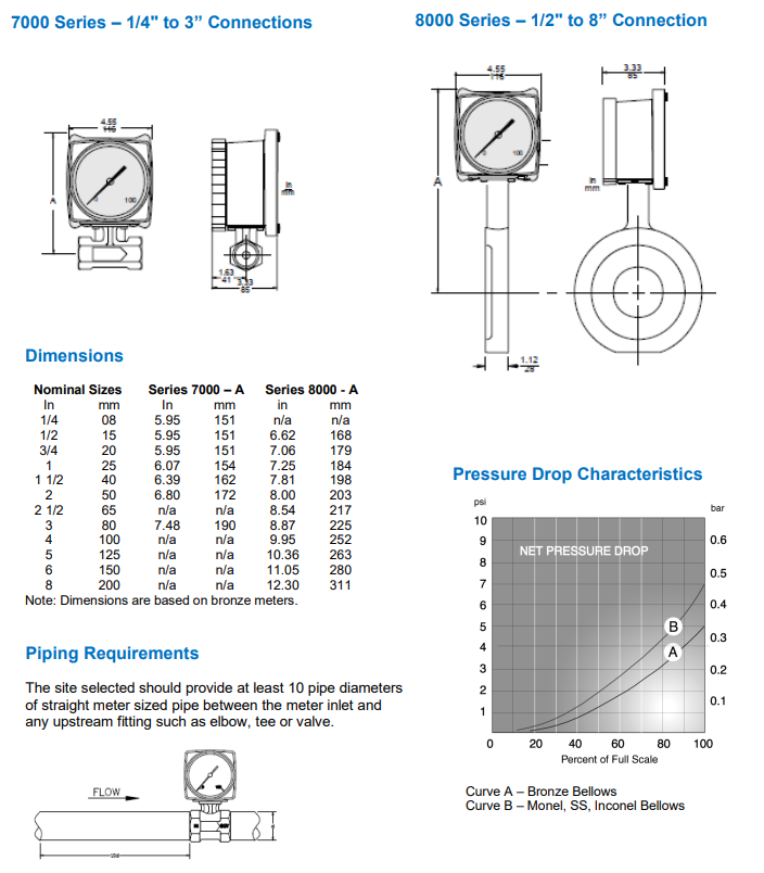
RCM flowmeter reference information. Confirm specifications against the selected model.
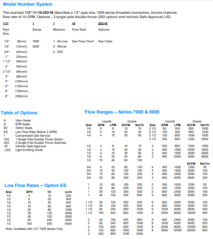
Additional RCM reference information for configuration and installation planning.
Optional switching arrangements provide one or two adjustable flow setpoints for alarms or equipment interlocks. Transmitter configurations are also available for connection to a PLC, recorder or monitoring system.
Check the signal specification before ordering. RCM W2/W3 transmitter outputs are linear with differential pressure and require linearisation in the receiving device to obtain flow. Do not assume every 4–20 mA option provides a signal directly proportional to flow.
If the main requirement is a flow alarm or interlock, also see the RCM Flo-Gard II liquid flow switch.
Contact us for pricing and availability. Include the following details so the meter can be selected for your operating conditions:
For a replacement meter, provide a photograph of the existing dial and nameplate, together with the complete model code.