- Out-of-Stock
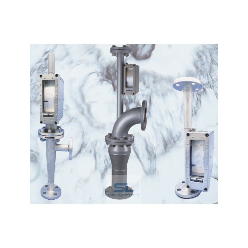

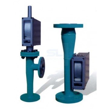
The Ryutai Kogyo EM series metal tube variable area flowmeter measures flow with a magnetically coupled indicator. Select local indication or additional electrical functions to suit your installation.
Select a Ryutai Kogyo EM series flowmeter around the process conditions and the way the measurement will be used. A local dial may be sufficient for operator checks; remote monitoring, consumption records or alarm functions require the appropriate instrument configuration.
For purchasing and maintenance teams, the complete specification should identify the fluid, flow range, connection arrangement, wetted materials and electrical requirements. An EM family code alone does not define a complete order.
| Parameter | Series information |
|---|---|
| Measuring principle | Variable area, with magnetic coupling to the indicator |
| Fluids | Clean liquids, gases and steam; model restrictions apply |
| Body sizes | 15A–150A; model-dependent |
| Standard measuring span | 10:1, corresponding to 10–100% of full scale |
| Indication accuracy | ±1.5% of full scale |
| Analogue output accuracy | ±2.0% of full scale |
| Resin-float allowance | Add ±1.5% of full scale to the applicable accuracy specification |
| Standard material | SUS304; alternative materials and linings depend on model |
| Standard connection | JIS 10K FF flange |
| Pressure and temperature | Depend on construction, flange rating, flow direction and selected functions |
| Power | Not required for local instantaneous indication; electrical functions have separate supply requirements |
The catalogue covers the following family codes. Use the complete code from a quotation or nameplate when requesting an instrument, replacement or technical clarification.
| Catalogue family codes | Selection requirement |
|---|---|
| EMC, EMU, EMD | Confirm the exact construction, connection arrangement and required measuring range. |
| EMW, EMX, EMY, EMR | Confirm body size, fluid service and installation dimensions. |
| EMT, EMG, EMH, EMJ, EMK, EMS | Confirm the application-specific construction and available functions. |
These codes identify families rather than interchangeable meters. Include all subsequent numbers and letters when supplying an existing model reference.
| Your requirement | What to specify in the enquiry |
|---|---|
| Read flow at the pipework | Dial units, minimum and maximum flow, and the direction from which the operator needs to read the scale. |
| Send flow to a PLC or recorder | Required signal, available power supply, receiving-device input and cable arrangement. |
| Record accumulated volume | Whether a local total, an external counting signal or both are needed, together with the required volume units. |
| Detect high or low flow | Alarm thresholds, number of alarm points and the contact behaviour required by the receiving equipment. |
Confirm the selected combination on the quotation. Do not assume that a transmitter includes every alarm, display or totalising function.
Provide minimum, normal and maximum operating flow rather than selecting by pipe diameter alone. This helps establish whether the proposed scale is useful during normal operation as well as at peak demand.
For liquids, include density and viscosity at the operating temperature. For gases, identify the gas composition, pressure and temperature, and state whether the flow units refer to operating conditions or a defined reference condition.
For steam, specify the steam condition and required mass or volume units. Include start-up conditions if they differ significantly from normal running conditions.
Fluid suitability: Magnetic fluids and fluids containing magnetic particles can interfere with the measuring mechanism. Disclose any solids or contamination before selecting the instrument.
Ryutai identifies the EM series as the replacement range for discontinued MCF-V, MCF-II and MCF-H instruments. However, the available constructions and flow ranges differ, so a replacement requires an application review.
Start with the information on the Ryutai MCF flowmeter replacement page. Send the existing nameplate, dial scale, installation dimensions and wiring diagram where available.
Retain the original installation details until the replacement specification has been confirmed. Matching the connection size alone does not establish mechanical or electrical interchangeability.
Contact us for pricing and availability. Include the fluid, flow range, operating conditions, pipe connections, quantity and required output functions.
For a new installation, a simple pipe sketch helps explain the available space and flow direction. For an existing installation, photographs of the instrument and nameplate help identify the specification that needs to be matched.