- Out-of-Stock
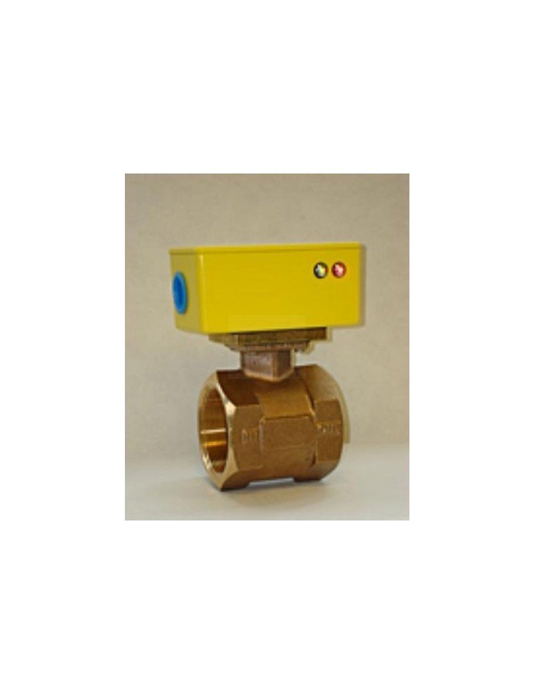
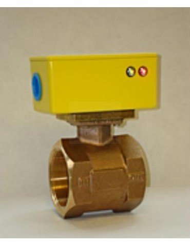



RCM Flo-Gard II liquid flow switches detect when flow crosses a selected setpoint, providing a contact signal for an alarm or equipment interlock. Applications include cooling-water circuits, chillers and compatible process-liquid systems.
Monitor liquid flow at a selected operating threshold with the RCM Flo-Gard II flow switch. Its switching contacts can provide an input to an alarm, relay or equipment control circuit when flow rises or falls through the configured setpoint.
For a cooling-water or process-liquid installation, specify both the normal operating flow and the flow level at which action is required. This helps select an appropriate range and switch arrangement.
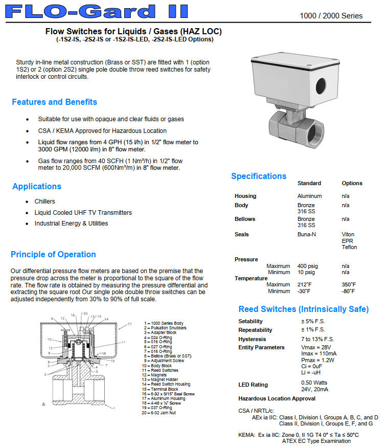
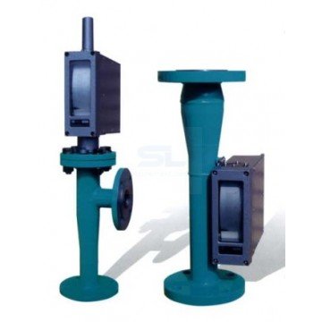
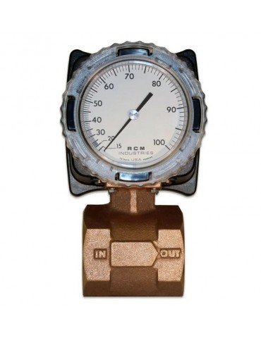
RCM Flo-Gard II reference illustration. Construction and options depend on the selected configuration.
The switch provides the contact signal; the connected control system determines the alarm, shutdown or other response.
A flow-induced differential pressure moves a bellows assembly. A magnet attached to the bellows actuates the reed switch as it passes the selected switching position.
SPDT contacts provide normally open and normally closed connections. Select the contact arrangement and control logic to suit the required response to increasing or decreasing flow.
| Option | Function | Selection guidance |
|---|---|---|
| 1S2 | One SPDT reed switch | For one switching threshold. |
| 2S2 | Two independently adjustable SPDT reed switches | For two thresholds, such as separate low-flow and high-flow signals. |
| LED | Visual switching-status indication | Useful when checking operation locally. Confirm the electrical requirements. |
| IS | Intrinsically safe configuration | Specify the hazardous-area classification and required approval when ordering. |
| Parameter | Specification / selection note |
|---|---|
| Standard maximum process temperature | 100°C; confirm compatibility with the selected seals and construction. |
| Maximum operating pressure | 400 psig, approximately 27.6 bar gauge. |
| Published minimum operating pressure | 10 psig, approximately 0.69 bar gauge. |
| Switch setability | ±5% of full scale. |
| Switch repeatability | ±1% of full scale. |
| Hysteresis | 13% of full scale for general-purpose versions; 7–13% for intrinsically safe versions. |
| Body and bellows options | Bronze or 316 stainless steel, depending on configuration. |
| Seal options | Buna-N, Viton, EPR or PTFE, subject to the selected specification. |
Understanding switch performance: Setability describes how closely the switching threshold can be adjusted. Repeatability describes consistency over repeated operation. Hysteresis is the separation between actuation and reset; these figures should not be treated as flow-reading accuracy.
The general-purpose contacts are rated up to 10 W, 125 V AC or 175 V DC, with a maximum switching current of 350 mA. All applicable limits must be respected together; the maximum voltage and current cannot automatically be used simultaneously.
Use the contacts with a suitable control input or interface relay. Do not assume they can directly switch a pump motor or another high-power load.
Intrinsically safe versions have different electrical limits. Confirm the supplied unit’s certification, control drawing and associated circuit requirements before installation.
Contact us for pricing and availability. Please include: